Volume Graphics
Only a little over a hundred years ago, cars were just beginning to replace horses as the standard form of transport. Leaping forward to this decade, car manufacturers worldwide are once again in transition, planning substantial moves away from sole reliance on the internal combustion engine (ICE) to a cleaner, greener future centered around reliable, efficient EV motor.
But how can manufacturers be confident that such a rapid shift from ICE to EV power will come with the same reliability and performance consumers have come to expect from gasoline-based engines? What is the most accurate approach to properly inspecting each electric motor, right down to the very last hairpin connection?
Modern industrial computed tomography (CT) software analysis is already providing many of the insights needed for final inspection and early process improvement of electric motors.
A brief history of the electric motor
The Egger-Lohner C2 Phaeton, which looks rather like a horse-drawn relic from the olden days, is not quite the first electric racecar that comes to mind, but in September 1899, it won a 25-mile (40km) road race in Berlin by a full 18 minutes. This model of EV ran on an octagonal electric motor, named for the shape of its housing, at a top speed of 22mph (35km/h).

EVs today are much faster and more efficient. While there’s over a century separating modern cars from the Egger-Lohner, the same heart beats at the core of each vehicle: an electric motor.
The idea behind the electric motor has remained largely unchanged since its conception. Most of them have a spinning rotor and a stator mounted in the housing creating a magnetic field when a current flows through the windings. Rapidly changing magnetic fields create torque around the rotor’s axis and set it in constant motion, which generates the mechanical energy needed to turn the gears of the car. A crucial element in powering this rotation is the copper wiring that comprises the stator’s internal coils. The first generation of electric motors used bundled coils with circular cross-sections.
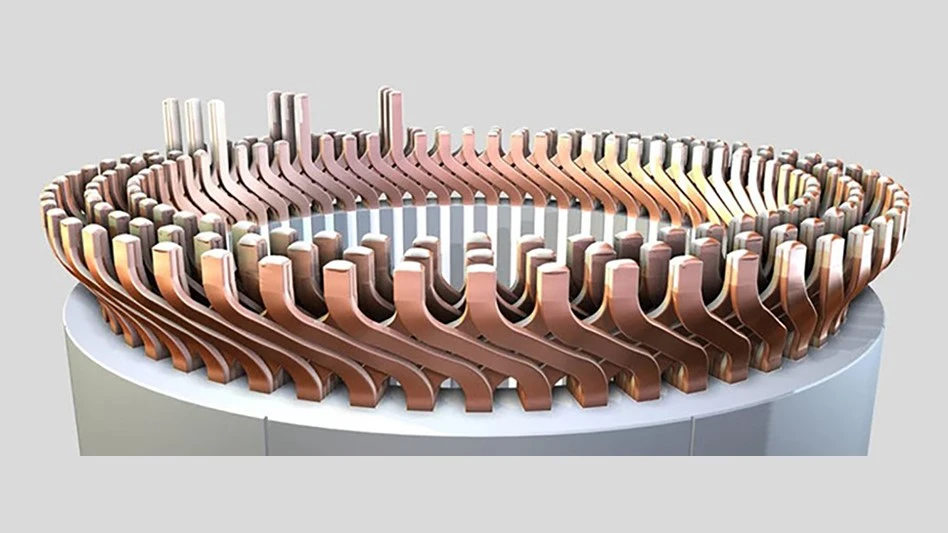
More recently, this design has been optimized into hairpin winding technology. Unlike conventional round-wire winding, “hairpin” stators contain tightly packed, hairpin-shaped pieces of copper wire with rectangular cross-sections. Several layers of interlocking wires produce a superior slot fill, which drives higher sustained output, and the open ends of the wires are welded together to close the electric circuits. These highly critical hairpins ensure enhanced performance, continuous power flow, and high reproducibility.
This development has revolutionized the EV industry, and hairpin stators can now be found in nearly every EV.


Hairpin advantages
The hairpin’s flat, rectangular wire strategy has some design and processing challenges, but is much more efficient than traditional round-wire motors. The hairpin motor is more compact, lighter, and provides more electrical contact surfaces. Performance-wise, a hairpin stator can reduce the effective material cost by 8% to 12%, increase acceleration, lower noise, and reduce system costs by roughly 15%. There’re also fewer connectivity gaps than in round wire, although this can remain an issue for hairpin-designed motors.
Hairpin inspection and the welding challenge
The switch from conventional round-wire winding to hairpin technology is a leap industries are still managing and learning from. Manufacturers of hairpin electric motors have a deep stake in realizing the highest possible level of conductivity and output from their motors.
Conductivity is dependent on hairpins having clean welds and low porosity at critical points. However, the welding joints at the ends of hairpins aren’t as “seamless” as they may appear to the eye. Welding seams aren’t visible using X-ray technology because the pins are melted into a unified material, making quality inspection more difficult. They may contain pores introduced by the welding process itself. This factor potentially reduces the cross-section area of the copper bar and lowers conductivity.

The time required to manually inspect these parts and welded connection points for porosity or fractures can be quite extensive. A fully automated, inline CT-inspection approach carefully accounts for the porosity and potential defects of the welding seam. There are innate challenges to this method, but technical issues can be addressed and made practical through highly automated analysis software.
Because the welding process takes place after assembly, hairpins are always CT-scanned along with the housing, which can lead to a lot of artifacts in the scan. Combined with the flexible, variable shape of the hairpins, this makes it nearly impossible to use a CAD model as a reference to align the object and get a clear idea of the state-of-the hairpins in the stator.
Nonetheless, there’s a way to refine the inline inspection process and drastically reduce the man-hours necessary for any remaining manual inspection, using advanced software analysis.
Advanced software inspection
Porosity analysis is not a new solution, but with the subvoxel accuracy and refinement options offered by advanced software solutions, product engineering can drastically improve the precision of the detected defect volume as opposed to earlier methods where the detection of a defect was only limited to voxel size. What does this mean for hairpin technology in electric motors?

The first major challenge is determining the geometry of the welded section, especially since the top of the welding seam is round and cannot be seen on a CAD model. This requires aligning the object using a “golden” mesh, calculated from the average of several scans, and a region of interest (ROI) functionality, to determine the analysis area.
Because such meshes more accurately reflect the actual shape of the part, a process called registration can be used to align the stator volume in each scan against the golden mesh. This lets engineers easily identify the analysis area and create an ROI pattern to define it. Such a method ensures minimum deviations between parts. It’s ideal for plastics and other materials that may get deformed in production, like hairpins. It can also be used to reverse-engineer an average shape so that random manufacturing deviations of single parts have less impact on the results. Creating a golden mesh also allows for mesh compensation and manufacturing geometry correction.
After defining an important analysis area, the second challenge is calculating and tolerancing the porosity of each welding seam. For this, a subvoxel-accurate algorithm can be used on dedicated, additional ROIs acquired by using CMM-like features of the software. This function takes place while applying any defined tolerances based on the volume of defects that need to be addressed. Finally, using a projection mode approach offers more accurate information on the remaining cross section for the current in the welding seam.

By including the ROI functionality in the mix, more accurate information on the hairpin is acquired. From there, based on results, better automation of the process is possible, which saves 5-10 minutes for a complete stator scan as opposed to 15 minutes for one weld. Overall, by ensuring a more seamless and reliable quality-control process, the need for significant manual inspection is avoided. Automation can greatly reduce the analysis time and man-hours needed to inspect, produce, and manufacture critical parts in an electric engine.
Deep dive inspection
Automated porosity detection software is ideal for analyses run on a series of CT scans, especially if they are affected by artifacts or simple deviations in gray value caused by scanning time. This is because while fixed, absolute gray values can change, specifying percentages in “relative mode” will differ only slightly. This is a much more adaptive approach that can save time, reduce errors caused by scanner deviation, and more accurately reflect the actual defect area.
Another key timesaver for the workflow is the use of a golden surface, which basically acts as a reference part if no CAD is available. It’s also useful when produced parts are more similar among themselves than to their CAD model. In this case, an average object is created out of the scans of several stators, which reflects real-world situations much more accurately than CAD.
This “golden stator” then serves as a standard against which all stators are aligned for analysis. Based on this alignment, geometry elements are imported and used to align slices and create precise rectangular ROIs on the parts under review, in this case, the hairpin welding seam used for porosity analysis.
As EVs evolve and mature, continuous improvement tools such as CT analysis help with final quality inspection and in understanding production processes, their variations, and the early design issues impacting the “as-manufactured” end part. CT analysis saves engineering time, material costs, and improves throughput, leading to more profitable and sustainable outcomes for vehicle manufacturers.
Latest from EV Design & Manufacturing
- Pushing the boundaries of electric vehicle cable testing
- CMMC requirements and your business
- Safer cells yield lighter battery packs
- Find out what 2025 holds for design and manufacturing
- Nuvve selects Tellus as hardware supplier for electric vehicle charging portfolio
- Thermwood to demonstrate large-scale additive manufacturing technology at JEC World 2025
- Automation For All | Okuma CNC Automation Solutions
- A compact machine for big EV ideas